MACHINE SAFETY FEATURES
MACHINE SAFETY FEATURES
MACHINE SAFETY FEATURES
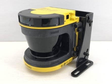
Area Safety Scanners
Safety area scanners detect the presence of people or objects within a defined area and trigger appropriate safety measures. These scanners use laser technology to create a protective field or zone around the automated equipment.
- Area Monitoring: Safety area scanners are capable of monitoring a designated area, typically in a 2D or 3D configuration, based on the specific model. They can detect the presence of people, vehicles, or other objects within the monitored zone.
- Range and Field Configuration: Safety scanners have adjustable ranges and field configurations, allowing customization to suit the specific requirements of the equipment and workspace. The range can vary from a few centimeters up to several tens of meters, depending on the model.
- Safety Zones: Safety area scanners define safety zones or areas where personnel are not allowed to enter during equipment operation. If someone or something enters the safety zone, the scanner sends a signal to the control system to stop or slow down the equipment to prevent accidents.
- Flexibility: Many safety area scanners offer flexible configuration options, including the ability to define multiple safety zones or to set up virtual barriers within the monitored area. This flexibility allows for customization to suit the layout and requirements of different automated equipment.
- Safety Outputs: When the safety area scanner detects an object or person in the protected zone, it generates safety outputs that can be used to trigger appropriate safety actions. These outputs can be connected to the control system of the equipment, leading to immediate machine shutdown or other safety measures.
- Integration with Control Systems: Safety area scanners are typically integrated into the overall safety system of the automated equipment. They can communicate with the control system through safety protocols like Safety over EtherCAT (FSoE) or PROFINET Safety. This integration ensures seamless interaction and synchronization between the scanner and the equipment’s control system.
- Diagnostic and Monitoring Capabilities: Many safety area scanners provide diagnostic and monitoring functions to detect potential malfunctions or faults. They can monitor the integrity of the emitted laser beams, analyze the detection performance, and provide status information to operators or maintenance personnel.
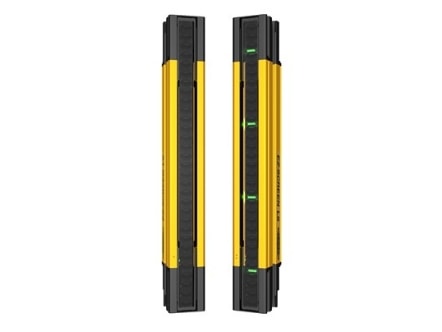
Light Curtains
Light curtains, also known as safety light barriers or optical safety devices, are commonly used on automated equipment to safeguard workers by detecting their presence in hazardous areas. Light curtains use infrared or visible light beams to create an invisible safety barrier, typically in the form of parallel beams across the entrance or perimeter of a hazardous zone. They are a popular alternative to physical barriers like fences or gates, as they allow for the free movement of objects or personnel while maintaining safety.
Here are some key features and functions of light curtains on automated equipment:
- Presence Detection: Light curtains are designed to detect the presence of objects or personnel within their field. When someone or something interrupts one or more of the light beams, it triggers a safety response, such as stopping or slowing down the equipment.
- Beam Configuration: Light curtains consist of a series of transmitters and receivers that emit and detect light beams. The number of beams and their spacing can vary depending on the application and level of safety required. More beams provide higher resolution and accuracy in detecting objects.
- Protective Height: Light curtains are available in different sizes, allowing for protection at various heights. The protective height is the vertical coverage of the light curtain, and it can be customized to match the specific requirements of the equipment and workspace.
- Response Time: Light curtains have fast response times, typically in the millisecond range, ensuring quick detection and reaction to objects or personnel entering the hazardous area. This rapid response helps minimize the risk of accidents.
- Safety Outputs: When a light curtain detects an object or person interrupting the light beams, it generates safety outputs that are connected to the control system of the automated equipment. These outputs can trigger safety measures such as emergency stop signals, machine shutdown, or activation of warning alarms.
- Cascading and Blanking: Light curtains often support cascading and blanking functions. Cascading allows multiple light curtains to be connected in series, expanding the protected area. Blanking enables selective deactivation of specific light beams to accommodate openings for the passage of materials or objects while maintaining safety in other areas.
- Integration with Control Systems: Light curtains are integrated into the overall safety system of automated equipment. They communicate with the control system through safety protocols such as Safety over EtherCAT (FSoE) or PROFIsafe, ensuring coordination between the light curtain and the equipment’s control functions.
- Self-Testing and Diagnostics: Many light curtains feature self-testing capabilities to verify their performance and detect any faults or malfunctions. These devices can perform periodic self-checks, monitor beam integrity, and provide diagnostic information to operators or maintenance personnel.
- Variants and Accessories: Light curtains come in various forms to suit different applications. Some variants include muting light curtains, which temporarily deactivate the safety function to allow the safe passage of objects, and hand detection light curtains, which are designed to detect the presence of hands near hazardous areas. Additionally, accessories such as mounting brackets and alignment aids facilitate easy installation and alignment of the light curtains.
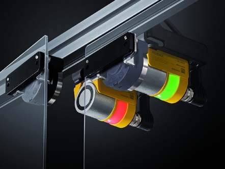
Door Interlocks
Door interlocks are safety devices commonly used on automated equipment to protect personnel and prevent access to hazardous areas during machine operation. These interlocks are designed to monitor the status of doors, gates, or access points and control the equipment’s operation accordingly. They play a crucial role in maintaining a safe working environment by preventing accidental contact with moving parts or hazardous processes.
Here are some key features and functions of door interlocks on automated equipment:
- Safety Monitoring: Door interlocks continuously monitor the status of doors or access points. They typically consist of sensors or switches that detect whether a door is open or closed. This monitoring ensures that the equipment operates only when the doors are properly secured and prevents unauthorized access.
- Interlock Logic: Door interlocks employ logic circuits or programmable safety controllers to control the equipment’s operation based on the door status. If a door is open or not properly secured, the interlock system sends a signal to the equipment’s control system to stop or prevent its operation, ensuring that hazardous processes or moving parts are not accessible.
- Sequential Control: In some cases, multiple doors or access points may be present on automated equipment. Door interlocks can implement sequential control, which requires a specific sequence of doors to be closed and secured before the equipment can start operating. This feature ensures that all potential hazards are adequately enclosed before initiating machine functions.
- Override and Bypass: Door interlocks often provide override or bypass functions to allow authorized personnel to temporarily override the interlock system under controlled circumstances, such as during maintenance or troubleshooting activities. These functions usually require additional safety measures and are subject to strict procedural controls to ensure worker safety.
- Safety Outputs: Door interlocks generate safety outputs that are connected to the equipment’s control system. These outputs can trigger safety measures such as emergency stop signals, machine shutdown, or activation of warning alarms when a door is opened or an interlock is compromised.
- Monitoring and Diagnostics: Many door interlock systems offer monitoring and diagnostic capabilities to ensure their reliable operation. They may include self-check features to verify the integrity of the interlock components, such as switches or sensors. Diagnostic information can be communicated to operators or maintenance personnel, allowing them to identify potential issues and take appropriate corrective actions.
- Integration with Control Systems: Door interlocks are integrated into the overall safety system of the automated equipment. They communicate with the control system through safety protocols like Safety over EtherCAT (FSoE) or PROFINET Safety, ensuring coordinated operation and synchronization between the interlock system and the equipment’s control functions.
- Compliance with Standards: Door interlocks must adhere to relevant safety standards and regulations, such as ISO 13849 or IEC 62061, depending on the industry and geographical location. Compliance ensures that the interlock system meets the required safety levels and provides reliable protection for personnel working with automated equipment.
Emergency Stops
Pushbutton emergency stops, also known as E-stop buttons or emergency stop switches, are essential safety devices used on automated equipment to provide a quick and easily accessible means of shutting down the equipment in emergency situations. These buttons are designed to be highly visible and easily identifiable, allowing operators to rapidly and effectively stop the machine’s operation in case of an impending hazard or unforeseen circumstances.
Here are some key features and functions of pushbutton emergency stops on automated equipment:
- Immediate Equipment Shutdown: The primary function of an emergency stop button is to instantly halt the operation of the automated equipment when pressed. It is a fail-safe mechanism that overrides normal control functions and interrupts power to the machinery, preventing further movement or potentially hazardous actions.
- High Visibility and Accessibility: E-stop buttons are typically designed with a distinctive color, such as red, and are prominently located and easily accessible to operators. This ensures that the button can be quickly identified and activated in emergency situations, even by personnel who are not familiar with the specific equipment.
- Latching or Momentary Action: Emergency stop buttons can have either a latching or momentary action. Latching buttons remain in the pressed position until manually reset, ensuring that the equipment stays deactivated until intentionally restarted. Momentary buttons require continuous pressure to keep the equipment shut down, and once released, they return to their normal state, allowing for a temporary stoppage.
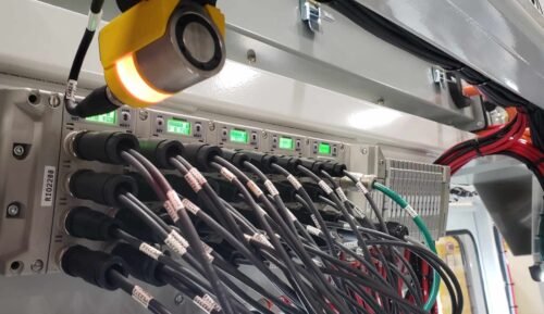
- Integration with Control Systems: Pushbutton emergency stops are integrated into the overall control system of the automated equipment. When the button is pressed, it generates a signal that is transmitted to the control system, triggering a safety response such as stopping the equipment, activating alarms, or initiating other predetermined safety procedures.
- Emergency Stop Circuits: To ensure the reliability and effectiveness of the emergency stop function, it is common to implement dedicated emergency stop circuits. These circuits use safety relays or safety controllers that are designed specifically for emergency stop applications. They provide redundancy and additional safety measures to ensure that the stop command is executed reliably.
- Reset and Restart: After an emergency stop has been activated, there is typically a separate reset button or procedure to restore the equipment to its operational state. This ensures that the machine does not automatically resume operation once the emergency situation has been resolved. Resetting the emergency stop requires a deliberate action, preventing accidental restarts.
- Compliance with Standards: Pushbutton emergency stops must comply with relevant safety standards and regulations, such as ISO 13850 or IEC 60947-5-5, depending on the industry and location. These standards define specific requirements for the design, functionality, and placement of emergency stop buttons to ensure their effectiveness in emergency situations.
- Labeling and Signage: To further enhance safety, emergency stop buttons are often accompanied by clear labeling or signage indicating their purpose and operation. This helps operators and personnel quickly identify the emergency stop button and understand its intended function.
Guard Doors / Hard Guarding
Hard guarding and access doors are essential safety features used in conjunction with automated equipment to protect personnel from potential hazards and provide controlled access to machinery. They are designed to physically enclose hazardous areas and prevent accidental contact with moving parts, high-energy sources, or dangerous processes.
- Hard Guarding: Hard guarding refers to the use of physical barriers, such as metal fences, enclosures, or panels, to create a protective barrier around hazardous areas of automated equipment. These barriers are typically made of durable materials that can withstand impacts and provide a sturdy physical barrier between personnel and potential dangers.
- Protective Enclosures: Hard guarding often involves enclosing entire sections or machines to prevent access to hazardous components or processes. These enclosures may have transparent panels, allowing operators to observe the equipment’s operation without compromising safety.
- Fixed Guards: Fixed guards are permanent barriers that are securely attached to the equipment, preventing access to hazardous areas. They are typically designed to be robust and tamper-proof.
- Interlocked Guards: Some hard guarding systems include interlocking mechanisms that disable the equipment’s operation when the guard is opened or removed. These interlocks ensure that the equipment cannot be operated while the guard is open or compromised, providing an additional layer of safety.
- Access Doors: Access doors are openings incorporated into hard guarding to provide controlled access to the equipment for maintenance, inspection, or other authorized activities. These doors are designed to be securely closed and may have interlocks to ensure that the equipment is not operational when the door is open.
- Locking Mechanisms: Access doors often feature locking mechanisms to prevent unauthorized access and ensure that they remain securely closed during equipment operation. These mechanisms can range from simple latches to more sophisticated locks and may require specific tools or keys for opening.
- Safety Interlocks: Access doors may be equipped with safety interlocks that prevent the equipment from operating when the door is open. The interlocks ensure that power is cut off or specific safety measures are activated when the door is not properly closed, minimizing the risk of


