SITUATION
The customer requirements’ included a complete closure assembly, inspection and packing machine featuring overhead conveyor systems.
OPPORTUNITY & IMPLEMENTATION
Step 1: Lid Infeed Conveyor:
Lids will enter the system via the infeed conveyor in single file open side down in random
radial orientation. The infeed conveyor is equipped with an overhead mounted Fanuc iR vision tracking
camera and conveyor speed tracking encoder. The camera tracks the position of every lid
and the radial orientation for the robotic pick and place robots.
Step 2: Robotic Pick and Placement:
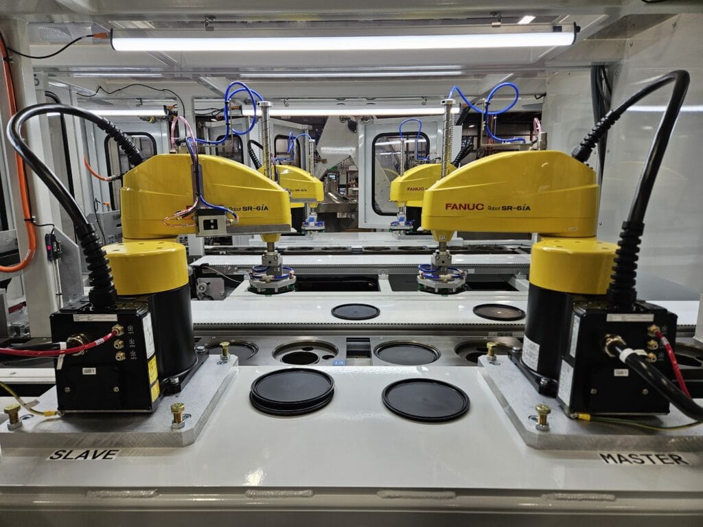
The robotic pick and placement station will be equipped with two (per side) Fanuc SR-6iA
SCARA Robots with R-30iB . Specialized end of arm
tooling on each robot will utilize vacuum to pick each lid. These robots will continuously
place the lids onto the indexing conveyor fixtures in the proper radial orientation.
Step 3: 2-Up Indexing Conveyor:
Each fixture will be designed to support and maintain positional orientation of
the lid through the assembly and stacking process. This machine includes one set of carrying
fixture tooling (see optional features for additional lid size fixtures). The indexing conveyor
assembly will be housed within a welded structural steel frame that will also support all
other system components.
Step 4: Cap Feed and Installation Station:
The cap feed and installation station will allow an operator to load caps into the 15 cubic foot
bulk pre-feeder in a large quantity. The pre-feeder will in turn meter dispense the cap
orientating system on demand. The caps will be orientated via vibratory feeder bowl open
side down in a single file for pick and placement two at a time. The pick and place
consists of a two-axis gantry that will shuttle back and forth to place and turn
the caps on with powered rotary actuators.
Step 5: Vision Inspection Station:
The lid assembly will be viewed and inspected prior to entering the indexing machine and
will eject rejected parts prior to entering. This inspection camera will be responsible for
determining proper label placement position and inspection for flash.
Step 6: 2-Up Up-Stacking Station:
The 2-up (per side) up-stacking stations will create vertically formed logs by lifting the lids
from underneath through the carrying fixtures.
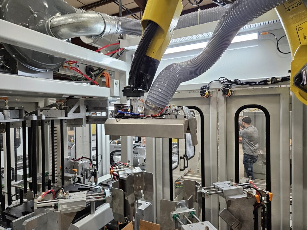
Step 7: Robotic Case Packing Station:
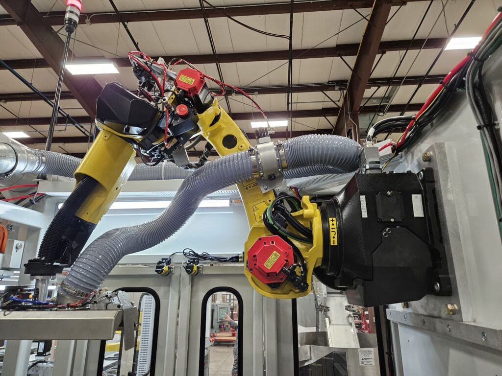
The robotic case packing station will consist of a Fanuc M-10iD/12 A-Cab R-30iB with a high
flow vacuum EOAT. The robot will be directed to the stacked log ready to be picked based on
obtaining the log count. The robot will then place the full log directly into the case based on
the programmed pack positions.
Step 8: Case Handling and Locating Station:
The cases will be introduced to the system via power roller conveyor and will follow a short
“U” travel pattern. The case conveyor will also allow integration of a case labelling station.
The case will enter the fill position where it is located and held in position by forming the
inside of the case creating a “shoe-horn effect” to allow as many lid’s as possible to be
inserted into the case.
DESIGN FEATURES & SPECIFICATIONS
(4) Lid infeed conv w/ overhead iR vision line tracking
(4) x 2 Fanuc SR-6iA Scara robots Specialized lid vacuum EOAT
(4) Cap bulk feeder elevator conveyors
(4) Cap orientate and feed systems
(4) Cap pick and place mechanism
(4) Torque application station
(4) Cap cross-thread check station Proposal
(4) Keyence Camera Solution, Specialized LED Lighting
(4) Independent servomotor control up stacking stations w/ accumulation magazines
(4) Vertical stacked log transfer actuator stations
(4) Fanuc M-10iD/12 A-Cab R-30iB case packaging robot
10 inch PanelView Performance HMI and safety PLC module
Approximate Machine Dimensions: 68’L x 24’W x 15’H
Power Requirements: 480 VAC, 3 Phase, 100A


