SITUATION
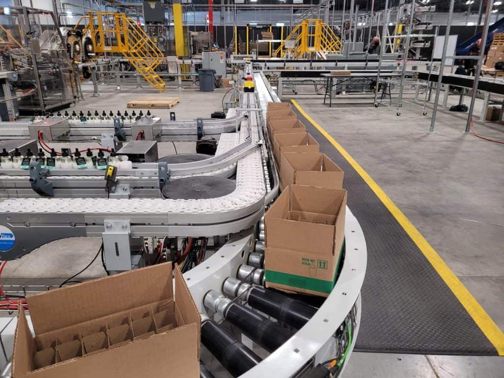
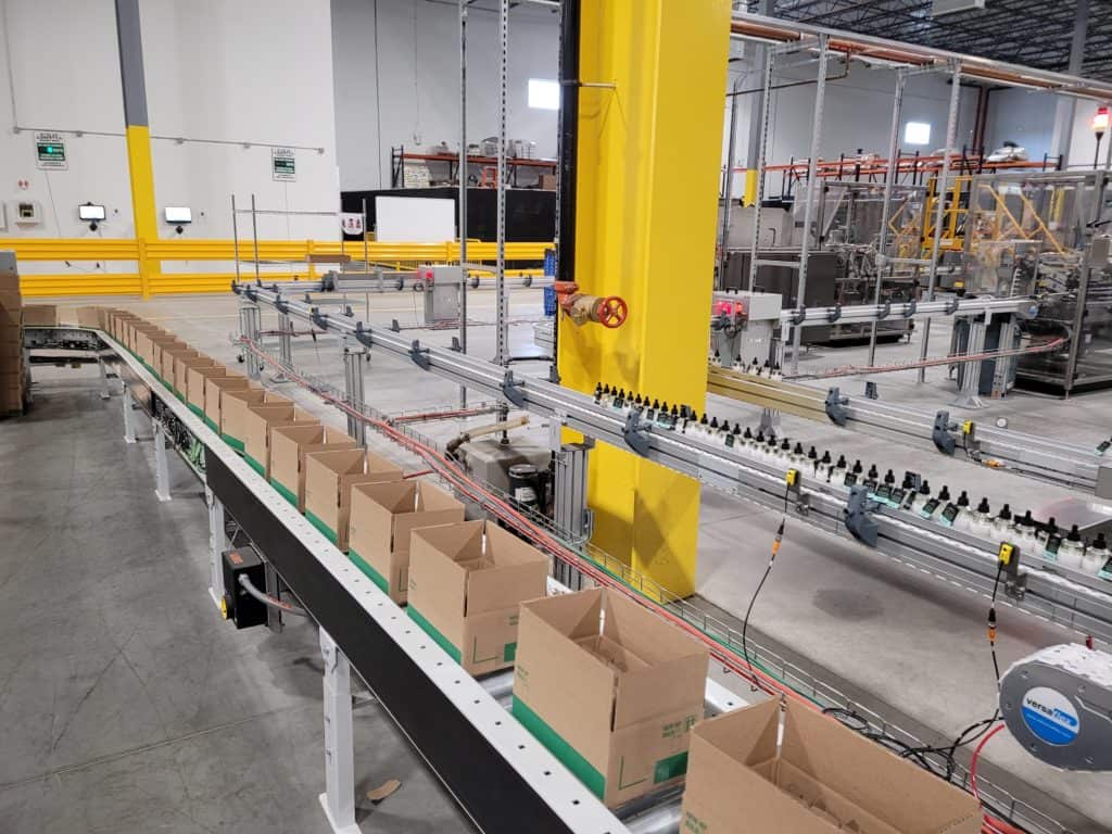
The purchasing customer expressed the desire to expand its Fill, Assemble, and Package operations. The former antiquated process was slower using unpredictable equipment with slow output rates. The line will have a design throughput rate of 275 vials per minute. The case-handling system will be sized to handle up to two lines for a total output of 550 vials per minute.
OPPORTUNITY & IMPLEMENTATION
The proposed and final stations include:
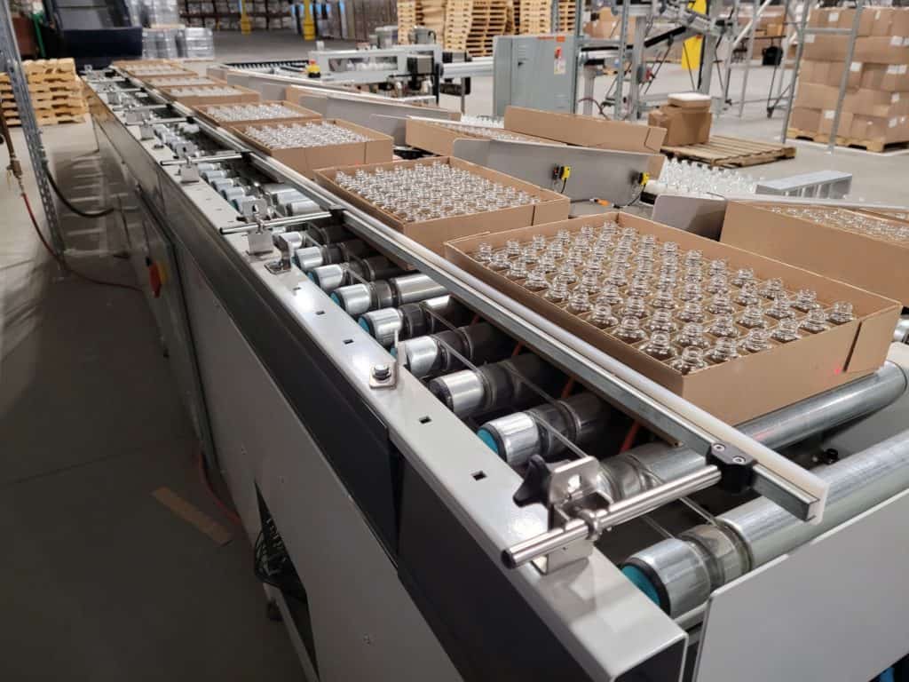
Bulb Placing Station– Four staff occupy the bulb loading station. Bulbs are transferred from the incoming cases to the pucks located on the puck conveyors.
Dunnage Out-Feed– Empty trays with bulb parts removed are placed on the dunnage out-feed conveyor.
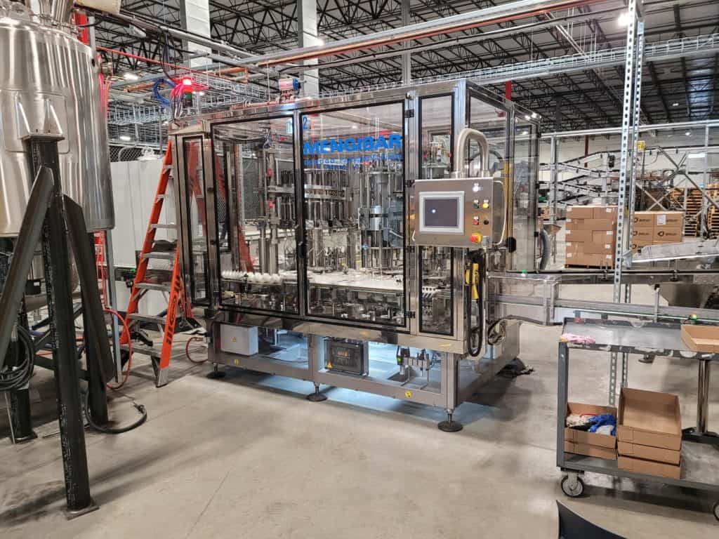
Filling Machine– The filling machine fills the bulbs with the specified amount of fluid and cap and wick parts are inserted into the bulb. The bulb then travels to the laser marker station of the machine.
Vortex Cooler– Vortex coolers located on the conveyor path keep the conveyor cool while traveling through the heat tunnel station. The coolers are self-sustained units requiring minimal operator intervention.
Shrink Band Dual Unwinder– The shrink band dual unwinder supplies shrink band material to the shrink sleeve applicator. Low material and ultrasonic sensors detect the material presence and signal the machine operator when maintenance is required.
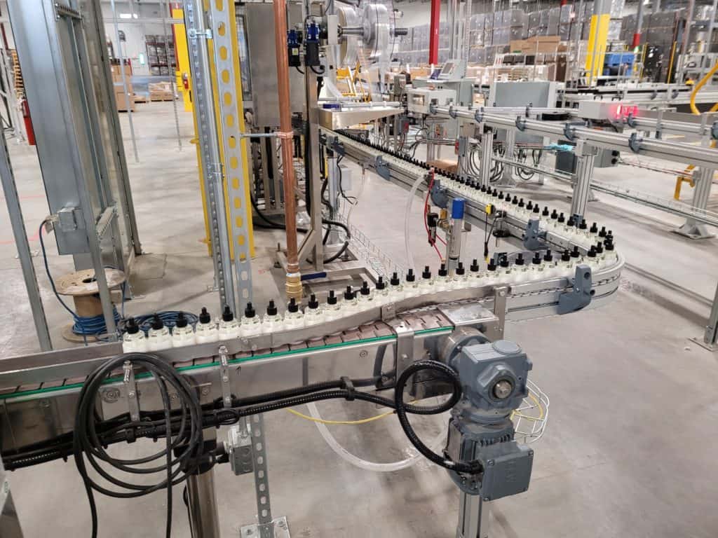
Tamper Evident Band Application– The shrink sleeve applicator applies the shrink band material to the bulbs.
Heat Tunnel- The heat tunnel heats the shrink-wrap material forming the lower bulb and upper cap parts.
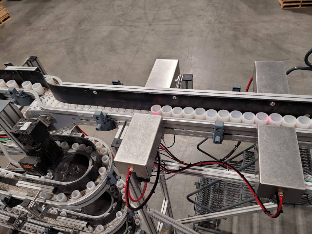
Reject Stations- Multiple reject stations located throughout the conveyor system verify part presence. Rejected parts are removed from the conveyor system and placed into specified reject stations.
Elastitag Application- The applicator uses a mechanism to pick the tags from the matrix and place them on the bottlenecks. There will be two applicators per line, and the machines will feature an automatic roll splice, allowing for zero downtime. The spent matrix roll will be collected in a waste bin.
Inspect and Reject- The vision inspection will verify that all components are present (cap, shrink sleeve, and elastic). A vision inspection station will be mounted next to the puck conveyor to capture an image of each assembly and flag incomplete items to be rejected. An actuator will divert a rejected assembly to a collection zone. This zone will also double as a QC inspection zone.
Case Forming- The case erector will erect and tape the bottom of the case. The case-forming machine continually provides an erected case to the partition inserter.
Partition Inserter- Fanuc M10 robots pick the partitions and insert them into the erected cases.
Manual Case Packing- The operators will pick the assemblies from the pucks and place them into the case partitions. There will be enough space for six (6) operators to work on one side.
Case Sealing & Labeling- Each case sealer will handle up to 15 cases per minute. Upon completion of the case, the applicator will print and apply the product identification label to the side of the case.
Puck Transfer Conveyors- Once the bulbs have been removed from the pucks, the pucks travel through elevated conveyors and are reintroduced into the bulb placing station.
DESIGN FEATURES & SPECIFICATIONS
- Tamper Evident Shrink Band Applicator
- Heat Tunnel
- Elastitag Applicator
- Inspection System
- Return Conveyor’s
- Allen-Bradley PLC controls package and HMI
- Print-and-Apply Label Applicator
- Robotic Partition Inserter
- Integrated Filling Machine
- Powered Roller ZPA Case Conveyors
- Fanuc M10 Robots

