SITUATION
The purchasing customer expressed the desire to expand into a new state-of-the-art production facility. This presented an opportunity to automate valve packaging and part inspection assemblies, ensuring a more consistent outcome by accurately regulating variability and improving processes while generating cost savings. The former antiquated process was predominantly manual and required a high degree of physical tasks and close monitoring.
OPPORTUNITY & IMPLEMENTATION
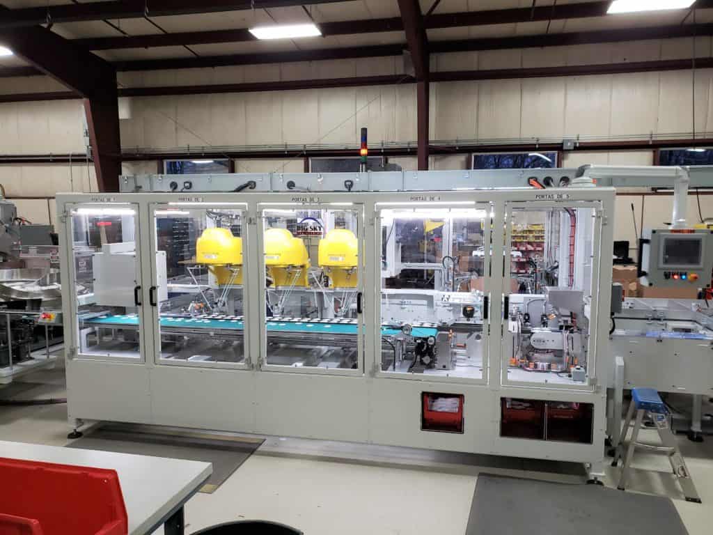
The project requirements included the machine to be completely autonomous. At its core, the requirements of this project required complex part inspection with a packaging rate of 160PPM. The HMI (Human Machine Interface) is configured for bilingual operation with the touch of a button. All machine guarding was required by NFPA 79 and OSHA standards. The machine was equipped with strategic service areas. The control system was UL-certified. All equipment met NEC standards as specified by the customer.
Final Stations Include:
Elevator Hoppers- Feed cap parts into the vibratory feeder bowls.
Feeder Bowls- The feeder bowls sort and supply the machine with cap parts.
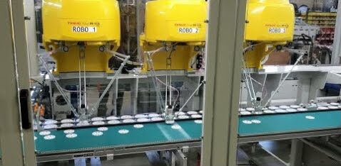
M1-iA Robot- Picks and places the adjuster cap part and places them on top of the lid cap part on the index conveyor.
Cam-Driven Press- The cam-driven press combines cap parts.
Inspection Point- Parts are inspected, air blasts contact the rejected parts and position them into the reject bin chute.
Accumulator- Assembled parts travel into the accumulator. The accumulator feeds parts into the in-feed conveyor in the packaging half of the machine.
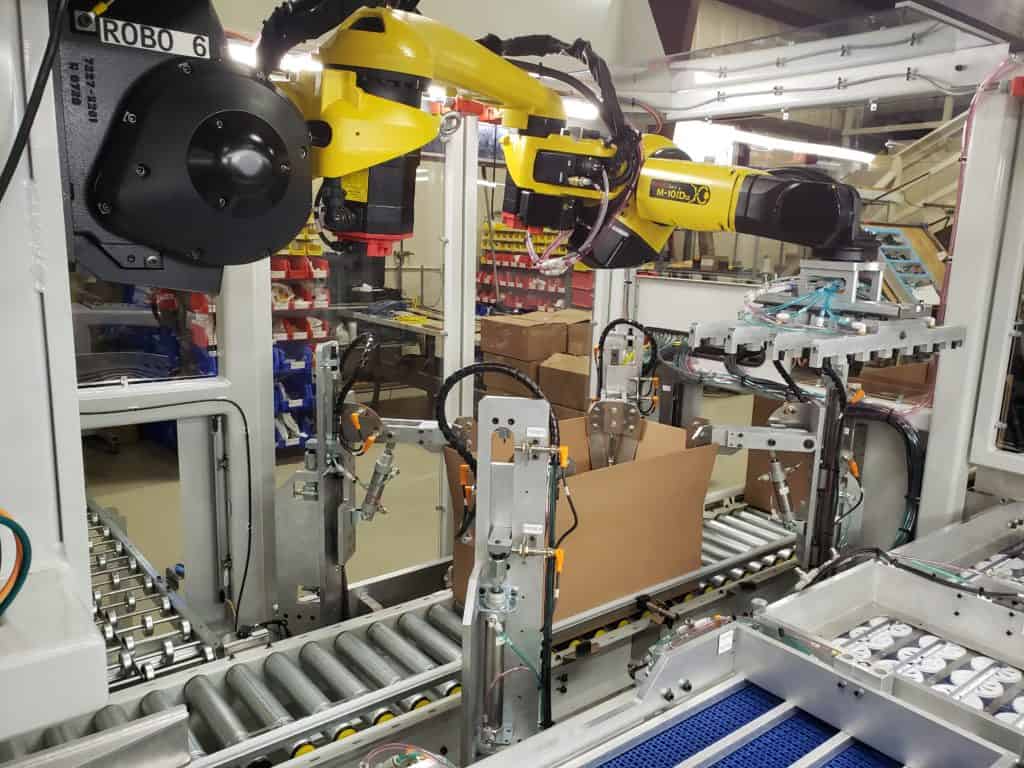
Case Handling- The cases are transferred into the box loading zone by powered roller conveyors. When the empty case advances in the case packing zone, box corner clamps secure the box into position. Vertical Clamps and locates will hold the case with plastic lining installed into position. When the cycle is completed, and the case is filled.
M-10iD Packing Robot– Full arrays of cap parts are picked and placed into the box located in the box loading zone.
Box Transfer– Powered Conveyor Rollers drive the box in and out of the box loading zone.
Box Locates– Box Locates hold the box in position.
Light Curtains– Light curtains protect the machine operator and bystanders from pinch points and electrical shock hazards.
DESIGN FEATURES & SPECIFICATIONS
- Three Fanuc M-1iA delta robots pick the top parts and place them onto the bottom parts while both are in motion
- Fanuc M-10iD robot with a custom vacuum end effector picks the entire layer and places it in the case
- a recirculation conveyor system that forms two lanes
- An overhead cam-driven press combines the plastic cap parts.
- Rate: 160PPM
- Stack Light Indicators and illuminated control buttons signal the machine operator of the machine’s current state.
- The machine HMI uses customary pictures & buttons for control overrides. All machine sequences can be operated in manual mode on the HMI.
- The reject bin located outside of the conveyor table isolates rejected parts.
- Powered roller conveyors for the box In-Feed and Out-Feed
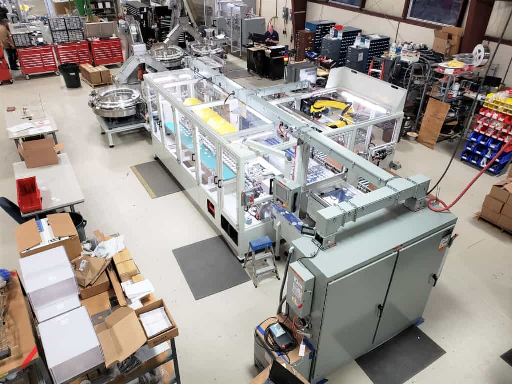
Approximate Machine Dimensions: 41’L x 41’W x 7.5’H
Power Requirements: 380VAC, 3 Phase, 100A
Pneumatic Requirements: 80PSI – 60 SCFM


